Wednesday, 4 November 2026

Pneumatic Diaphragm Valve Troubleshooting and Maintenance

Pneumatic Diaphragm Valve Troubleshooting, Maintenance and Failure Prevention

A pneumatic diaphragm valve can operate reliably for long periods when its components are correctly selected and maintained. However, like other process equipment, it can develop problems due to diaphragm wear, incorrect actuator settings, contaminated instrument air or changes in operating conditions.

The most common symptoms include external leakage, incomplete closure, slow response and inconsistent valve positioning.

Replacing the diaphragm immediately may appear to be the easiest solution, but it does not always address the actual cause.

A systematic troubleshooting approach helps maintenance engineers identify whether the problem originates in the process valve, pneumatic actuator or control system.


Understanding the Complete Valve Assembly

Before investigating a malfunction, distinguish the main operating systems.

The process valve contains the body, flexible sealing diaphragm and compressor mechanism.

The pneumatic actuator converts compressed-air pressure into mechanical movement.

Control accessories may include a solenoid valve, filter-regulator, positioner, limit switch and air tubing.

These components work together but can fail independently.

For example, a leaking actuator diaphragm may prevent proper movement without indicating damage to the process diaphragm.

Similarly, a damaged process diaphragm can cause fluid leakage even when the actuator operates normally.

Recognizing this difference is the first step toward accurate diagnosis.

Problem 1: The Valve Does Not Open

A valve that fails to open may have a pneumatic supply problem.

Check whether the actuator is receiving the required air pressure.

A closed isolation valve, blocked air line or malfunctioning filter-regulator can prevent adequate pressure from reaching the actuator.

If a solenoid valve controls the air supply, verify its command signal and appropriate electrical operation through authorized procedures.

For spring-return arrangements, determine whether air pressure is required to open or close the valve.

An air-to-open actuator may remain closed when its supply is interrupted.

Mechanical issues are also possible.

A damaged compressor connection, incorrect diaphragm assembly or actuator mechanism fault may restrict travel.

Do not attempt to force the valve open using excessive air pressure.

Problem 2: The Valve Does Not Close Completely

Incomplete closure may produce unwanted flow through a line that should be isolated.

Potential causes include inadequate actuator force, incorrect travel adjustment, diaphragm damage or deposits on the sealing surface.

First verify whether the actuator reaches its intended closed position.

If travel is incomplete, examine the air supply, control signal and mechanical operating mechanism.

If full travel occurs but process leakage continues, the sealing interface may require inspection.

A worn diaphragm or damaged body weir can prevent reliable shutoff.

Accumulated solids may also interfere with seating.

The corrective action must address the underlying condition rather than simply increasing the actuator closing pressure.

Problem 3: External Process Leakage

External leakage requires immediate attention, particularly when the fluid is hazardous or corrosive.

Potential leakage locations include the body-to-bonnet joint, damaged process diaphragm and pipe connections.

A diaphragm can deteriorate through repeated flexing, chemical incompatibility, excessive temperature or mechanical overstress.

Incorrect installation may create uneven compression and reduce sealing performance.

If leakage is suspected, follow the plant's approved isolation and containment procedures.

Do not loosen bonnet fasteners or attempt diaphragm replacement while the equipment remains pressurized.

After safe isolation, inspect the diaphragm and relevant sealing surfaces according to the manufacturer's maintenance instructions.

Problem 4: Pneumatic Air Leakage

Air escaping from the actuator is different from process fluid escaping from the valve body.

Possible causes include a damaged actuator diaphragm, worn seals, loose pneumatic connections or defective fittings.

A cracked pneumatic tube may produce a continuous air leak.

A leaking actuator chamber can also reduce available force and prevent the valve from reaching its required position.

Check instrument-air pressure and inspect accessible external connections during authorized maintenance.

Repeated air-pressure loss may require actuator seal replacement or a more detailed inspection.

Never assume the process diaphragm has failed simply because an air leak is heard.

Problem 5: Slow or Inconsistent Operation

Slow operation may result from restricted air flow, insufficient pressure, incorrectly adjusted speed controls or mechanical resistance.

Moisture and dirt in the pneumatic system can also affect response.

Inspect the filter-regulator and verify that the air supply meets the actuator manufacturer's requirements.

Where applicable, check solenoid exhaust passages and flow-control settings.

For a valve that cycles frequently, compare current opening and closing times with commissioning records.

A gradual increase in operating time may indicate developing friction or pneumatic restrictions.

Sudden changes may indicate a control-system or supply issue.

Problem 6: Unstable Positioning During Throttling

A pneumatically operated diaphragm valve fitted with a positioner may experience oscillation or poor position stability.

Possible causes include incorrect positioner calibration, unstable control signals, actuator friction or inappropriate control-loop tuning.

First identify whether the valve position is unstable or whether the process variable itself is fluctuating.

Review command signals, actual valve feedback and actuator-air pressure.

A valve with excessive friction may respond only after the control signal changes significantly.

This behavior can create inconsistent flow regulation.

Controller adjustments should not be used to conceal a mechanical problem.

Where precise modulation is required, verify that the valve was originally selected for the intended control range.

Problem 7: Premature Process Diaphragm Failure

Diaphragm life depends on material compatibility, mechanical design and operating conditions.

Chemical attack may cause swelling, hardening or cracking.

Excessive temperature can accelerate deterioration of certain elastomers.

Repeated flexing can eventually produce fatigue damage.

Abrasive particles may wear the diaphragm surface, particularly under unfavorable flow conditions.

Incorrect compressor alignment or excessive closing force can also shorten service life.

When repeated failures occur, compare the damaged component with the manufacturer's recommended material and installation procedure.

Simply installing another diaphragm of the same grade may lead to the same problem.

Preventive Maintenance Checklist

A practical maintenance program should include regular inspection of pneumatic accessories, valve operation and process performance.

Monitor instrument-air quality and confirm regulator settings.

Check accessible pneumatic fittings for leakage.

Verify opening and closing response against operating requirements.

Inspect external valve joints for evidence of leakage.

Review diaphragm replacement intervals based on actual service severity and operating cycles.

For modulating valves, monitor positioner performance and control stability.

The inspection frequency should be determined by service conditions and maintenance history.

Safe Diaphragm Replacement

Before opening the valve, isolate the process line using the approved procedure.

Depressurize and drain the valve, and verify the absence of hazardous fluid or stored energy.

Isolate pneumatic and electrical supplies and apply the required lockout controls.

Remove the actuator or bonnet assembly only as instructed by the manufacturer.

Inspect the diaphragm, compressor and sealing surface for wear or damage.

Install the correct replacement component using the specified orientation and fastening sequence.

Incorrect assembly can damage the new diaphragm or compromise the seal.

After reassembly, complete the required pressure, leakage and functional tests before returning the valve to service.

When Should the Actuator Be Replaced?

Actuator replacement may be necessary when internal components are damaged, corrosion is severe or the assembly cannot deliver the required thrust.

However, replacement should follow proper diagnosis.

A healthy actuator cannot overcome a fundamentally unsuitable valve selection.

If the process pressure or operating duty has changed, the original actuator may no longer be correctly sized.

Request a new engineering assessment rather than selecting a larger actuator without considering diaphragm loading.

Frequently Asked Questions

Why does a diaphragm valve leak after replacement?

Possible causes include incorrect installation, uneven fastening, damaged sealing surfaces or unsuitable replacement materials.

Can a pneumatic diaphragm valve operate without compressed air?

A spring-return actuator can move toward its specified failure position when air is lost. Normal controlled operation generally requires the intended pneumatic supply.

How frequently should diaphragms be replaced?

There is no universal replacement interval. Material, chemical exposure, temperature, pressure and operating cycles determine service life.

Can a positioner solve incomplete valve closure?

A positioner may correct a control-related issue, but it cannot repair damaged sealing surfaces or compensate for inadequate mechanical closing force.

Conclusion

Effective pneumatic diaphragm control valve maintenance requires an understanding of both the process sealing system and the pneumatic operating mechanism.

External leakage, poor shutoff, slow response and unstable positioning can have different causes.

A disciplined approach based on operating records, safe inspection and manufacturer-approved procedures helps prevent recurring problems.

FRETURE Techno Pvt. Ltd. provides industrial diaphragm control valve solutions for application-specific operating requirements.

For technical evaluation, share the valve data sheet, process conditions, actuator details and observed failure symptoms to support accurate diagnosis and appropriate corrective action.

Industrial Applications of Pneumatic Diaphragm Valves

Industrial plants handle an enormous variety of fluids. A chemical manufacturer may transfer an aggressive acid, while a water-treatment facility manages suspended solids. A pharmaceutical plant, meanwhile, may require a clean process environment with stringent contamination controls.

Although these applications appear different, they share a common requirement: dependable fluid isolation and flow management.

Pneumatic diaphragm valves are frequently considered because their flexible process diaphragm separates the working fluid from the valve's operating mechanism.

When combined with suitable materials and compressed-air actuation, this construction can support automated process control across several industries.

However, different applications demand different valve designs. Understanding those distinctions is essential for reliable performance.

Why Industry-Specific Valve Selection Matters

A valve that performs well in clean water may deteriorate rapidly when exposed to concentrated chemicals.

Similarly, a diaphragm designed for chemical resistance may not be suitable for abrasive slurry or repeated high-temperature sterilization.

The correct solution depends on more than the general valve type.

 Pneumatic Diaphragm Control Valves

Engineers must consider fluid chemistry, pressure, temperature, flow rate, operating frequency and maintenance requirements.

Body material, lining and diaphragm construction should be evaluated as a complete system.

Pneumatic actuation introduces another consideration: the plant must have an adequate and reliable compressed-air supply.

1. Chemical Processing Industries

Chemical manufacturing is one of the important application areas for diaphragm valves.

Process lines may transport acids, alkalis, specialty chemicals and other aggressive liquids.

Conventional valve components can experience accelerated deterioration when incompatible materials contact these fluids.

A diaphragm valve helps isolate the operating mechanism from the process stream.

Depending on chemical compatibility, a suitably lined body and PTFE-faced diaphragm may provide an effective solution.

Typical Chemical Applications

Pneumatic diaphragm valves may be considered for chemical transfer, dosing, mixing-system isolation and process utility distribution.

Automated actuation allows the valve to respond to production sequences without requiring manual operation at every location.

For example, a batch-processing plant may use pneumatic valves to direct different compatible liquids into a mixing vessel.

The control system opens the selected valve, verifies the operating position and closes the line when the transfer sequence finishes.

This approach can improve operating consistency when the complete automation system is correctly engineered.

Important Engineering Considerations

Not every corrosive chemical can be handled by the same diaphragm material.

Temperature and concentration can significantly affect compatibility.

Engineers should review chemical resistance data and confirm the suitability of the body lining, diaphragm and connected components.

2. Water and Wastewater Treatment Plants

Water-treatment facilities often require numerous automated valves.

These may operate in filtration systems, chemical dosing stations, treatment skids and process distribution lines.

Pneumatic diaphragm valves can be useful where suitable sealing, straightforward operation and compatibility with the treatment medium are required.

Chemical Dosing Systems

Water-treatment processes may use chemicals for pH correction, disinfection and other treatment functions.

The selected valve must resist the actual chemical solution.

An appropriately selected diaphragm valve can provide automated line isolation as part of the dosing system.

Filtration and Backwashing

Some filtration systems use automated valve sequences to direct water through different operating paths.

Pneumatic actuation supports repeatable opening and closing in accordance with the plant's control logic.

However, each valve must be selected for the pressure differential and operating frequency associated with the sequence.

Wastewater and Sludge

Wastewater can contain suspended solids, fibrous material and abrasive particles.

A straight-through diaphragm valve may be useful for certain compatible slurry applications because of its relatively open passage.

Nevertheless, high solids loading, large particles or severe abrasion can reduce diaphragm and lining life.

Actual media characteristics must be evaluated before selecting the valve.

3. Pharmaceutical and Biotechnology Applications

Pharmaceutical processing places strong emphasis on product quality, cleanliness and contamination control.

Specially designed hygienic diaphragm valves are used in various pharmaceutical and biotechnology systems.

Their internal geometry can help minimize difficult-to-clean regions when the complete design is intended for hygienic service.

The process diaphragm also separates the fluid path from the operating mechanism.

Typical Applications

Depending on the validated process and valve design, applications may include purified-water systems, process-media transfer, clean utility distribution and product-contact operations.

Automated valves can be integrated with batch-control systems to support repeatable manufacturing sequences.

Hygienic Design Requirements

An ordinary industrial diaphragm valve is not automatically suitable for pharmaceutical service.

Requirements may include specified stainless-steel grades, surface finishes, hygienic connections and traceable process-contact materials.

Some applications require compatibility with cleaning-in-place or sterilization-in-place procedures.

The diaphragm must withstand the actual cleaning agents and thermal cycling.

For relevant installations, ASME BPE requirements and project-specific hygienic design criteria may apply.

Material documentation and qualification evidence should be reviewed rather than assumed.

4. Food and Beverage Manufacturing

Food-processing systems often involve frequent cleaning and carefully controlled product handling.

Hygienic pneumatic diaphragm valves can support automated flow isolation in suitable applications.

However, service conditions vary significantly.

A valve used for an aqueous beverage may not be appropriate for concentrated syrup, fatty products or high-temperature cleaning cycles.

Food-contact material suitability must be verified for the intended jurisdiction and actual fluid.

Automation in Production Lines

Pneumatic actuation allows valves to operate as part of coordinated production sequences.

For example, valves may control the routing of compatible process fluids between tanks, equipment and cleaning circuits.

The benefits depend on correct valve sizing, instrumentation and control-system design.

A poorly selected valve can still cause pressure loss, cleaning difficulties or premature diaphragm failure.

5. Mining and Mineral Processing

Mining and mineral-processing facilities may handle abrasive liquid mixtures and suspended solids.

In selected lower-pressure applications, straight-through diaphragm valves can offer useful flow characteristics.

Their sealing method can also avoid exposing certain operating components directly to the slurry.

However, abrasive media can wear the diaphragm or body lining.

Particle size, concentration and flow velocity must be considered.

Pneumatic actuation may be useful where valves are operated remotely from control rooms.

For severe services, engineers should compare diaphragm valves with pinch valves and other slurry-handling equipment.

There is no universal solution for every abrasive fluid.

6. Oil, Gas and Petrochemical Utility Systems

Oil and gas facilities use many valve technologies, including ball, gate, globe, butterfly and control valves.

Diaphragm valves may serve selected auxiliary systems, chemical-dosing packages, treatment units and compatible low-pressure process duties.

They should not automatically be specified for high-pressure hydrocarbon or high-temperature steam applications.

Diaphragm materials and complete valve construction have service limitations that must be respected.

Where hazardous-area instrumentation is required, the solenoid, limit switch and related electrical accessories must meet the applicable installation requirements.

Process compatibility and actuator failure action are equally important.

7. Industrial Skids and Automated Packages

Packaged process equipment often combines pumps, filters, instruments and valves on a common skid.

Pneumatic diaphragm valves can support automated operation where the selected medium and service conditions are suitable.

Potential applications include treatment skids, chemical preparation units and process distribution systems.

For OEMs, compact assembly dimensions and accessible maintenance points can be valuable.

Actuator orientation, air tubing and access for diaphragm replacement should be considered during skid design.

Advantages Across Industrial Applications

Although every industry has different requirements, several benefits are common.

Pneumatic actuation provides remote operation and integration with control systems.

The flexible diaphragm separates the fluid from the operating mechanism.

Suitable construction can support reliable on-off service and selected throttling applications.

Various diaphragm materials and body linings allow engineers to evaluate different chemical duties.

Maintenance procedures may also be simplified because many designs permit diaphragm access without removing the entire body.

These benefits depend on correct design and operation.

Frequently Asked Questions

Which industries commonly use pneumatic diaphragm valves?

Chemical processing, water treatment, pharmaceuticals, biotechnology, food processing and selected slurry-handling industries are important application areas.

Are pneumatic diaphragm valves suitable for hazardous chemicals?

They may be suitable where materials, operating conditions and protective arrangements are correctly specified.

Can one diaphragm material serve every industry?

No. Chemical compatibility, temperature, fatigue resistance and cleaning requirements vary.

Are all pneumatic diaphragm valves hygienic?

No. Hygienic applications require specialized construction, suitable materials and relevant documentation.

Conclusion

Pneumatic diaphragm control valves can offer valuable solutions for automated process isolation and selected flow-control duties.

Their strongest advantage is not simply pneumatic operation. It is the combination of a flexible sealing barrier, suitable materials and application-specific valve construction.

FRETURE Techno Pvt. Ltd. provides diaphragm control valve solutions for industrial process requirements.

Selecting the correct configuration begins with understanding the fluid, operating conditions and expectations of the industry in which the valve will operate.

How to Select and Size a Pneumatic Diaphragm Valve: An Engineering Guide

Pneumatic Diaphragm Valve Selection & Sizing Guide

Selecting a pneumatic diaphragm valve involves more than matching its nominal diameter to a pipeline. The valve must withstand the process fluid, achieve the required flow capacity and close against the maximum expected differential pressure.

An undersized actuator may fail to achieve reliable shutoff. An unsuitable diaphragm can deteriorate prematurely, even when the valve body itself remains in excellent condition.

For mechanical engineers and EPC contractors, the best approach is to treat the valve, diaphragm, actuator and control accessories as one engineered package.

Start With the Actual Process Conditions

Before considering manufacturers or valve configurations, prepare a complete process data sheet.

Identify the process fluid, including its chemical composition and concentration. Record minimum, normal and maximum operating temperatures.

Specify the design pressure, maximum operating pressure and expected upstream and downstream conditions.

Flow requirements should include minimum, normal and maximum values. If the medium contains suspended solids, describe their approximate concentration, particle characteristics and likelihood of settling.

Also consider operating frequency.

A valve that opens twice per week faces different mechanical demands from one operating several hundred times each day.

These details help determine the suitable body pattern, diaphragm material and actuator operating range.

Step 1: Choose the Correct Valve Body Pattern

Weir-Type Construction

A weir-type valve uses a raised sealing surface inside the body.

The diaphragm moves through a comparatively short distance to achieve closure.

This construction is frequently considered for clean liquids, chemical processing and selected throttling duties.

However, the weir restricts the passage and affects pressure drop.

For high-flow services, engineers should review the actual valve flow coefficient rather than assuming full-pipe capacity.

Straight-Through Construction

A straight-through diaphragm valve provides a less obstructed flow path when open.

This can be useful for compatible slurries, viscous liquids and fluids containing suspended particles.

The longer diaphragm movement can increase mechanical demands on the closure assembly.

Diaphragm fatigue, actuator stroke and required force should therefore be reviewed carefully.

No body pattern should be selected solely because it is described as suitable for slurry service.

Actual solids characteristics remain important.

Step 2: Evaluate Body and Lining Materials

The valve body's pressure-containing material must withstand the service conditions.

Cast iron or ductile iron may be suitable for certain utility and water applications within their design limitations.

Carbon steel can be considered where pressure, temperature and process compatibility permit.

Stainless steel may be preferred where corrosion resistance or cleanliness is important.

For aggressive chemicals, a lined valve can help separate the process medium from the metallic body.

Possible lining materials include hard rubber, elastomers and fluoropolymers, depending on the selected design.

Body lining is not simply an optional coating.

Its thickness, bonding method, temperature resistance and compatibility with the fluid influence reliability.

A chemically compatible lining may still be unsuitable if pressure, temperature or mechanical conditions exceed its allowable limits.

Step 3: Select the Diaphragm Material

The process diaphragm is among the most important components.

Its material must tolerate chemical exposure, repeated flexing and the required sealing load.

EPDM Diaphragm

EPDM is often evaluated for water and certain compatible chemical applications.

It should not be assumed suitable for hydrocarbon-rich service.

NBR Diaphragm

NBR can be suitable for selected oil-related applications, subject to the fluid composition and operating temperature.

PTFE-Faced Diaphragm

PTFE offers broad chemical resistance, making it attractive for many corrosive services.

However, mechanical flexibility and operating pressure remain important.

PTFE-faced diaphragms often rely on an elastomeric backing.

Compatibility must therefore be checked for the complete composite construction.

Other Elastomer Options

FKM, butyl and other specialty materials may be available.

Their suitability depends on temperature, chemical concentration and the complete process environment.

Always request manufacturer confirmation for the specified duty.

Step 4: Calculate Required Flow Capacity

Valve selection should account for the desired flow rate and permissible pressure drop.

For a simplified incompressible liquid application, the required flow coefficient can be estimated using:

Kv = Q × √(SG / ΔP)

Where:

  • Kv represents the metric flow coefficient.

  • Q is the liquid flow in cubic metres per hour.

  • SG is liquid specific gravity relative to water.

  • ΔP is the pressure drop in bar.

For example, suppose water flows at 20 m³/h and the permitted valve pressure drop is 0.25 bar.

The simplified calculation gives:

Kv = 20 × √(1 / 0.25) = 40

This provides an initial capacity target.

The final selection must account for the manufacturer's actual flow data, valve opening, fluid properties, potential cavitation and operating conditions.

The simplified relationship is not suitable for every fluid or flow regime.

Where accurate modulation is required, consider valve characteristics across all expected operating cases.

Step 5: Determine Pneumatic Actuator Thrust

A common specification mistake is selecting an actuator only by the valve's nominal size.

The actuator must generate sufficient force throughout the required stroke.

Closing force depends on line pressure, pressure differential, diaphragm geometry, diaphragm material and the valve's mechanical design.

Available pneumatic force depends on actuator effective area, air supply pressure and opposing spring forces.

A basic pneumatic force relationship is:

Force = Effective Area × Pressure Difference

However, this is not a complete actuator-sizing calculation.

The design must also account for spring compression, friction, operating direction and the force required to achieve the specified shutoff performance.

For spring-return assemblies, the required thrust must remain available at the limiting operating condition.

The actuator must also provide sufficient travel for full valve opening.

An undersized stroke can reduce achievable flow capacity.

Step 6: Specify the Required Fail Position

Instrument-air failure is an important process safety consideration.

A spring-to-close arrangement may be appropriate where shutting the pipeline is required.

A spring-to-open arrangement may be preferred where maintaining flow is safer.

Double-acting actuators require a defined pneumatic circuit and a separately assessed air-failure response.

The engineering specification should state the intended failure position clearly.

Terms such as direct acting and reverse acting can be interpreted differently across equipment types.

For critical services, the plant's approved process safety philosophy governs the selection.

Step 7: Select Automation Accessories

A basic on-off valve may require a solenoid valve, filter-regulator and position indication.

Remote monitoring can require limit switches or proximity sensors.

A modulating valve may need an electro-pneumatic positioner and suitable feedback instrumentation.

The air supply must be clean, dry and regulated within the actuator manufacturer's specified limits.

Check voltage, instrument-air pressure, electrical enclosure requirements and control-system interface.

For hazardous areas, certification must match the installation jurisdiction and the actual equipment supplied.

Step 8: Review Standards and Testing

The applicable standards depend on valve construction, service and project specifications.

EN 13397 addresses metallic diaphragm valve construction.

Control applications may require additional sizing or performance considerations under applicable IEC or EN control-valve standards.

Specify hydrostatic testing, seat leakage acceptance, diaphragm material verification and functional testing as required.

Do not assume a particular certification or test result simply because the product belongs to an established valve category.

What Should an RFQ Include?

A technically useful request for quotation should identify the valve type, nominal size, pressure rating, end connections, fluid, temperature, body and diaphragm materials, operating differential pressure and required flow.

Include instrument-air availability, failure position, solenoid voltage, position indication and installation constraints.

For throttling applications, provide the expected control range.

Request a general arrangement drawing, dimensional information, relevant material documentation and proposed actuator-sizing confirmation.

Frequently Asked Questions

Can a larger actuator compensate for an unsuitable diaphragm?

No. Additional force cannot correct chemical incompatibility, inadequate temperature resistance or an unsuitable body pattern.

Should valve size always match the pipeline?

Not necessarily. Flow capacity, pressure loss and system design may justify a different valve size, subject to appropriate piping transitions.

Why does PTFE diaphragm selection affect actuator sizing?

Composite diaphragm constructions can have different stiffness and closing-force requirements from elastomer-only diaphragms.

Conclusion

A reliable pneumatic diaphragm valve begins with accurate process information.

Correct sizing must consider the body pattern, fluid compatibility, diaphragm flexibility, available flow capacity, actuator thrust and instrument-air conditions.

Freture Techno Pvt. Ltd. offers Pneumatic Diaphragm Control Valve configurations for industrial applications.

For efficient technical evaluation, provide a complete process data sheet and request design-specific actuator and material recommendations before finalizing the purchase.

Pneumatic Diaphragm Valves: Types, Working Principle and Industrial Benefits

Every industrial pipeline needs a dependable way to control fluid movement. In chemical processing, water treatment and pharmaceutical manufacturing, that challenge becomes more complicated when the medium is corrosive, abrasive or sensitive to contamination.

Pneumatic diaphragm valves offer a practical solution by combining a flexible sealing element with compressed-air actuation. Unlike conventional valves that rely on a metal disc, ball or plug as the main closure member, a true diaphragm valve uses a flexible membrane to seal the flow passage.

Its construction can provide effective process isolation while keeping the operating mechanism separated from the fluid.

Understanding the available designs helps engineers select equipment based on actual process conditions rather than general product descriptions.

What Is a Pneumatic Diaphragm Valve?

A pneumatic diaphragm valve is a linear-motion valve operated by compressed air. The valve contains a flexible process diaphragm that moves toward or away from a sealing surface inside the body.

When the diaphragm presses against the sealing surface, fluid flow stops. As it lifts, the passage opens and fluid moves through the valve.

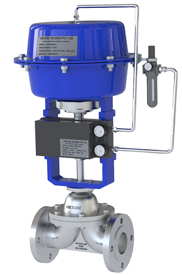
Pneumatic Diaphragm Valve

A typical assembly consists of a valve body, flexible diaphragm, compressor mechanism, bonnet, stem and pneumatic actuator.

The diaphragm separates the process medium from the operating mechanism. Consequently, conventional sliding stem packing is generally unnecessary as the primary process containment barrier.

This feature makes diaphragm valves attractive for applications where controlling external leakage and protecting mechanical components from process exposure are important.

How Does a Pneumatic Diaphragm Valve Work?

The operating sequence begins when compressed air enters the actuator.

Air pressure creates a mechanical force that moves the actuator stem. The stem transfers motion through the compressor mechanism to the process diaphragm.

During closing, the compressor presses the diaphragm against the valve's sealing surface. During opening, the compressor retracts and allows the diaphragm to lift.

The exact air-to-open or air-to-close arrangement depends on the actuator configuration.

A spring-return actuator can move the valve toward a predetermined position when instrument-air pressure is lost. Other designs use air pressure for both opening and closing.

The actuator must generate enough force to overcome fluid pressure, diaphragm resistance and mechanical friction.

A diaphragm valve should therefore be evaluated as a complete assembly, not simply as a body fitted with an air cylinder.

Types of Pneumatic Diaphragm Valves

1. Weir-Type Pneumatic Diaphragm Valve

The weir-type construction contains a raised sealing section inside the valve body.

The diaphragm moves downward onto this raised weir to close the passage.

Because the required diaphragm movement is comparatively short, this arrangement can be suitable for frequent operating cycles and selected throttling applications.

Weir-type designs are widely considered for chemical processing, water treatment and other services where flexible isolation is beneficial.

The raised weir introduces a flow restriction, so pressure loss and flow capacity must be assessed during sizing.

2. Straight-Through Pneumatic Diaphragm Valve

The straight-through design has a relatively unobstructed flow passage when fully open.

The diaphragm closes against a lower body contour rather than a pronounced raised weir.

This arrangement is often selected for slurries, suspended solids and viscous media where maintaining a less restricted flow path is valuable.

However, straight-through designs can require greater diaphragm movement.

The resulting stroke, diaphragm strain and actuator force must be considered when selecting the equipment.

3. Pneumatic Diaphragm Control Valve

Some diaphragm valves are equipped with positioners for controlled intermediate opening.

Instead of operating only in fully open or closed positions, the actuator adjusts diaphragm travel in response to a process-control signal.

These arrangements can regulate liquid flow in suitable services.

However, a standard on-off diaphragm valve should not automatically be considered a precision control valve.

Accurate modulation depends on the valve's flow characteristics, usable control range, actuator sizing and positioner performance.

Pneumatic Actuator Configurations

Normally Closed

In a typical spring-return, air-to-open configuration, the spring closes the valve when air pressure is removed.

This arrangement may be selected where isolation is the required response to an instrument-air failure.

Normally Open

In an air-to-close, spring-to-open arrangement, the valve opens when actuator air pressure is released.

This configuration may be appropriate where maintaining flow is the safer process response.

Double Acting

A double-acting actuator uses compressed air to provide movement in both directions.

Its behavior during air failure depends on the complete pneumatic circuit. It should not be assumed to remain reliably in its last position without suitable supporting equipment.

The specified failure position should always be confirmed through the plant's process safety assessment.

Major Components and Their Functions

The valve body contains the process fluid and defines the flow path. The diaphragm provides the flexible sealing interface, while the compressor distributes closing force.

The bonnet supports the operating assembly and separates it from external surroundings.

The pneumatic actuator converts compressed-air pressure into controlled linear movement.

Additional equipment may include a solenoid valve, air filter-regulator, position indicator, limit switch, speed controller and electro-pneumatic positioner.

Each accessory serves a different purpose.

For example, a solenoid valve directs actuator air, whereas a positioner helps maintain a requested intermediate valve position.

Common Diaphragm Materials

Material selection strongly affects valve reliability.

EPDM is used in various water and selected chemical applications, depending on the exact composition and operating temperature.

NBR may be appropriate for certain oils and compatible industrial fluids.

PTFE-faced diaphragms are often considered where chemical resistance is important. These frequently use an elastomeric backing to support movement.

Other elastomers may be available for specialized duties.

No diaphragm material is suitable for every chemical.

Compatibility must be confirmed using the actual fluid composition, concentration, temperature and operating conditions.

Advantages of Pneumatic Diaphragm Valves

Process Isolation

The diaphragm separates the fluid from the operating mechanism, helping reduce exposure of actuator-related components to aggressive media.

Remote Automation

Pneumatic actuation enables integration with automated process sequences, plant control systems and remote operating stations.

Suitable Sealing Characteristics

Correctly selected diaphragms can provide dependable closure against their intended sealing surfaces.

Actual shutoff performance depends on diaphragm condition, pressure differential and assembly design.

Maintenance Accessibility

Many constructions permit diaphragm inspection or replacement without removing the entire valve body from the pipeline, provided safe isolation and the manufacturer's maintenance procedure are followed.

Flexible Application Range

Different body geometries, linings and diaphragm materials support a variety of industrial services.

Nevertheless, each combination has its own pressure, temperature and flow limitations.

Engineering Limitations to Consider

Diaphragm valves are not universal replacements for ball, butterfly or globe valves.

High temperatures can accelerate elastomer deterioration. Excessive pressure differential can increase the closing force required.

Abrasive solids may wear the diaphragm and lining, while aggressive chemicals can cause swelling, hardening or loss of elasticity.

Straight-through arrangements may require more actuator travel, and weir-type arrangements can introduce additional pressure loss.

High-cycle operation also requires careful attention to diaphragm fatigue.

Engineers should evaluate these limitations before selecting a product.

Where Are Pneumatic Diaphragm Valves Used?

Common applications include chemical dosing lines, wastewater treatment systems, filtration plants, compatible slurry-handling duties and automated utility systems.

Specialized hygienic diaphragm valves are also used in pharmaceutical and biotechnology operations.

However, hygienic construction, material traceability and sterilization compatibility are additional requirements, not automatic features of every diaphragm valve.

Frequently Asked Questions

Are pneumatic diaphragm valves suitable for throttling?

Certain designs can provide throttling control, particularly when equipped with appropriate actuation and position feedback. The usable control range must be confirmed.

Can they handle corrosive chemicals?

They may be suitable when the body lining, process diaphragm and connected components are compatible with the fluid.

What happens when compressed air fails?

The response depends on the actuator and pneumatic circuit. Spring-return arrangements can provide defined fail-open or fail-closed behavior.

Are pneumatic diaphragm valves suitable for steam?

Only specifically rated assemblies should be considered. Steam temperature and cycling may exceed the limits of common diaphragm materials.

Conclusion

Pneumatic diaphragm valves combine flexible process sealing with automated linear operation.

Their suitability depends on body geometry, diaphragm material, fluid conditions and actuator design.

For chemical, water-treatment and process automation projects, correct engineering selection can improve operating reliability and maintenance planning.

FRETURE Techno Pvt. Ltd. provides industrial Pneumatic Diaphragm Control Valve solutions, with configurations selected according to application requirements.

For a technical enquiry, share the process medium, pressure, temperature, flow conditions and preferred actuator failure position. These details form the basis of a dependable valve selection.

Tuesday, 25 March 2025

Optimizing Fluid Control with Diaphragm Control Valves

In industries requiring precise fluid regulation, Diaphragm Control Valves are widely used due to their reliability and performance. These valves play a crucial role in managing flow rates, pressure, and fluid composition across various industrial applications, including pharmaceuticals, food processing, water treatment, and chemical processing.

What is a Diaphragm Control Valve?

A Diaphragm Control valve is a linear motion valve designed to regulate fluid flow by using a flexible Diaphragm to Control the opening and closing of the valve. Unlike traditional valves with complex mechanical parts, diaphragm valves offer a simple yet effective design that minimizes contamination and enhances durability.

Diaphragm Control Valve

Key Design Features of Diaphragm Control Valves

  1. Diaphragm Mechanism – The Diaphragm is a flexible membrane that moves up and down to regulate the flow of fluid. It is typically made of materials such as rubber, PTFE, or other elastomers, providing excellent chemical resistance and longevity.

  2. Body Material – Depending on the application, diaphragm control valves can be manufactured from stainless steel, cast iron, or plastic (PVC, PP) to withstand corrosive and high-pressure environments.

  3. Actuation System – These valves can be operated manually, pneumatically, or electrically, providing options for automated process control.

  4. Flow Regulation – The valve offers precise throttling control, making it ideal for modulating applications where accuracy is essential.

  5. Hygienic Design – Commonly used in pharmaceutical and food industries, diaphragm control valves feature a crevice-free design that prevents fluid contamination.

Advantages of Diaphragm Control Valves

  • Leak-Free Operation: The diaphragm creates a tight seal, reducing the risk of leaks.

  • Corrosion Resistance: Suitable for aggressive chemicals and high-purity applications.

  • Minimal Maintenance: Fewer moving parts result in lower maintenance costs and longer service life.

  • Versatility: Available in various sizes and materials to suit different industrial requirements.

Applications of Diaphragm Control Valves

Diaphragm Control Valves are extensively used in industries where contamination-free and precise fluid control is necessary. Some key applications include:

  • Pharmaceutical Industry – For sterile and high-purity fluid handling.

  • Water Treatment Plants – Regulating water and chemical dosing.

  • Food & Beverage Industry – Ensuring sanitary fluid control.

  • Chemical Processing – Managing highly corrosive fluids.

Conclusion

Diaphragm Control Valve offer efficient, reliable, and contamination-free fluid regulation across various industries. Their ability to withstand harsh conditions, along with precise control mechanisms, makes them a preferred choice for critical fluid handling applications. Selecting the right Diaphragm valve ensures long-term performance and operational efficiency, making it an integral component in process automation.

Pneumatic Diaphragm Control Valves: Enhancing Flow Control Efficiency in Industrial Applications

Pneumatic diaphragm control valves play a crucial role in regulating fluid flow in industrial processes. These valves are widely used in industries such as oil & gas, pharmaceuticals, water treatment, and chemical processing, where precision, reliability, and automation are essential. With their ability to provide accurate flow control while minimizing energy consumption and maintenance costs, these control valves have become indispensable components in modern industrial setups.

What is a Pneumatic Diaphragm Control Valve?

These control valve is a type of valve that uses compressed air to actuate a diaphragm, which in turn regulates the fluid flow. This control mechanism ensures smooth and precise adjustments in pressure and flow rates, making these valves ideal for automated systems. The key components of these control valve include:

  • Diaphragm: A flexible membrane that responds to air pressure variations.

  • Actuator: Converts pneumatic signals into mechanical movement.

  • Valve Body: The main housing that directs and controls the fluid flow.

  • Positioner (Optional): Enhances control precision by adjusting the diaphragm’s movement based on input signals.

Depending on the operational requirements, these valves can be direct-acting (where the diaphragm opens the valve) or reverse-acting (where the diaphragm closes the valve).

Pneumatic Actuator Diaphragm Control Valve Manufacturer in India

Key Features and Advantages

1. High Precision Flow Control : These control valves are designed to modulate flow with high accuracy. They provide fine control over process variables, ensuring stability and efficiency in industrial operations.


2. Durability and Corrosion Resistance : Manufactured using robust materials such as stainless steel, PTFE, or elastomers, these valves can withstand harsh industrial environments, including exposure to corrosive chemicals and extreme temperatures.


3. Low Maintenance Requirements : Unlike electrically operated valves, pneumatic diaphragm control valves have fewer moving parts, resulting in minimal wear and tear. This extends the lifespan of the valve and reduces the need for frequent maintenance.


4. Energy Efficiency : Since these valves use compressed air instead of electricity, they contribute to lower operational costs. Their efficiency makes them a preferred choice for industries looking to optimize energy consumption.


5. Leak-Proof Design : The diaphragm mechanism ensures a tight seal, preventing leakage and ensuring safe operation, particularly in hazardous environments where fluid containment is critical.

Types of Diaphragm Control Valves

Depending on application needs, different types of pneumatic diaphragm control valves are available:

  • Globe Control Valves: Ideal for precise flow modulation in various industrial applications.

  • Angle Seat Valves: Suitable for high-pressure environments where durability and responsiveness are required.

  • Three-Way Control Valves: Used for mixing or diverting flows in process industries.

  • Sanitary Diaphragm Valves: Specifically designed for pharmaceutical and food industries, ensuring hygienic fluid control.

Applications Across Industries

These control valves are extensively used across multiple industries due to their reliability and versatility:

  • Pharmaceutical Industry: Used in sterile environments to regulate fluid flow in drug manufacturing processes.

  • Chemical Processing: Capable of handling aggressive chemicals while maintaining operational safety.

  • Water Treatment Plants: Helps in regulating pressure in filtration and distribution systems.

  • Oil & Gas Sector: Plays a critical role in controlling steam, gas, and fluid movement in pipelines.

Choosing the Right Diaphragm Control Valve

When selecting these control valve, it is essential to consider the following factors:

  • Pressure and Temperature Ratings: Ensure that the valve meets the operational requirements of the application.

  • Compatibility with Process Fluids: The valve material should be resistant to the fluid type being controlled.

  • Automation Integration Capabilities: Some systems may require smart positioners for enhanced control.

  • Compliance with Industry Standards: Look for valves certified under ISO, FDA, or other relevant standards to guarantee quality and safety.

These control valves are essential for ensuring efficient and precise fluid control in industrial applications. Their ability to provide leak-proof performance, durability, and energy efficiency makes them a preferred choice for industries requiring high-performance flow control solutions. Investing in high-quality pneumatic diaphragm control valves can lead to improved system performance, reduced downtime, and enhanced operational safety.

Wednesday, 12 March 2025

What is the Difference Between a Diaphragm and a Butterfly Valve? Where is it Used?

Valves play a crucial role in fluid control across various industries, ensuring the smooth regulation of liquids and gases. Among the most commonly used valve types are diaphragm valves and butterfly valves, both of which serve distinct purposes based on their design and function. Understanding their key differences and applications can help industries select the right valve for their specific needs.

What is a Diaphragm Valve?

A diaphragm valve is a type of valve that uses a flexible diaphragm to regulate fluid flow. The diaphragm is typically made of elastomeric or synthetic materials such as PTFE or EPDM, which provide chemical resistance and durability. This valve operates by pressing the diaphragm against the valve seat to stop flow or lifting it to allow fluid passage.

Key Features of Diaphragm Valves

  • Leak-proof design: Provides a tight seal, reducing leakage risks.

  • Hygienic and sterile operation: Commonly used in industries requiring contamination-free processes, such as pharmaceuticals and food processing.

  • Corrosion resistance: Suitable for handling aggressive chemicals and slurries.

  • Precise flow control: Works well for throttling applications.

What is a Butterfly Valve?

A butterfly valve is a rotary valve that uses a circular disc mounted on a rotating shaft to control fluid flow. When the disc is turned parallel to the flow, the valve opens, and when turned perpendicular, it closes. The quarter-turn mechanism allows for quick and efficient flow regulation.

Key Features of Butterfly Valves

  • Compact and lightweight: Takes up less space compared to other valve types.

  • Quick operation: Requires only a 90-degree turn to fully open or close.

  • Cost-effective: Economical solution for large-diameter flow control.

  • Suitable for high-flow applications: Used in water treatment, HVAC systems, and industrial pipelines.

Key Differences Between Diaphragm and Butterfly Valves

FeatureDiaphragm ValveButterfly Valve
DesignUses a flexible diaphragm to control flowUses a rotating disc to regulate flow
OperationLinear motion (up/down)Rotary motion (quarter-turn)
Sealing PerformanceProvides a tight, leak-proof sealModerate sealing capability, may require additional gaskets
Application SuitabilityIdeal for sterile, corrosive, and precise flow controlBest for large-diameter, high-flow applications
MaintenanceRequires diaphragm replacement over timeLow maintenance, simple disc replacement
Flow ControlPrecise throttling capabilityBest suited for on/off control with limited throttling

Where are These Valves Used?

Both diaphragm and butterfly valves are widely used across industries, but their applications differ based on fluid type, pressure requirements, and flow control needs.

Common Applications of Diaphragm Valves

  1. Pharmaceutical and Biotechnology: Used for sterile fluid handling in cleanroom environments.

  2. Food and Beverage: Ensures hygienic fluid transfer in dairy, brewing, and beverage processing.

  3. Chemical Processing: Handles aggressive chemicals and slurries with high corrosion resistance.

  4. Water Treatment: Regulates chemical dosing and filtration systems.

Common Applications of Butterfly Valves

  1. Water and Wastewater Treatment: Controls water distribution and sewage systems efficiently.

  2. HVAC Systems: Regulates air and water flow in heating, ventilation, and cooling systems.

  3. Power Plants: Used in steam and cooling water applications.

  4. Oil and Gas Industry: Controls fuel flow in pipelines and storage facilities.

Choosing the Right Valve for Your Needs

When selecting between a diaphragm valve and a butterfly valve, consider the following factors:

  • Fluid Type: Diaphragm valves are ideal for corrosive and sterile applications, while butterfly valves work best for water, air, and non-corrosive fluids.

  • Pressure Requirements: If a leak-tight seal is critical, a diaphragm valve is the better option. If quick shut-off and large flow capacity are needed, a butterfly valve is more efficient.

  • Industry Standards: Certain industries, such as pharmaceuticals and food processing, require diaphragm valves to meet strict hygiene regulations.

Conclusion

Both diaphragm valves and butterfly valves serve vital roles in fluid management, each offering unique advantages. Diaphragm valves excel in precision control, chemical resistance, and sanitary applications, whereas butterfly valves are favored for cost-effective, high-flow operations. By understanding their differences and applications, industries can make informed decisions to optimize their fluid handling systems.

Pneumatic Diaphragm Valve Troubleshooting and Maintenance

Pneumatic Diaphragm Valve Troubleshooting, Maintenance and Failure Prevention A pneumatic diaphragm valve can operate reliably for long peri...